
In this post I would like to share a PCB project that I have done using the Altium Designer program.
Components:
4 Buttons
21 capacitors
4 Diodes
3 LEDs
4 Relays
4 Piezo Buzzers
41 Transistors
3 MOSFETs
86 Resistors
1 Tranformator
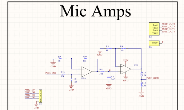
4 OPAMPs
1 PIC18f45K20 microcontroller
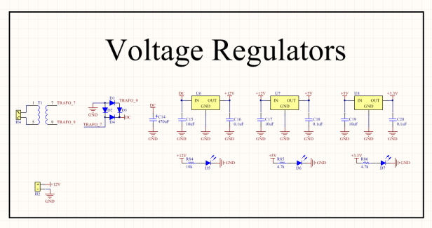
3 Voltage Regulators
1 Relay driver
8 Headers
The PCB has a lot of features including which can be used in multiple applications. The location of a sound can be found using its piezo microphones, RGB LED strips can be driven using the 12 VDC outputs and motors can be driven with the relays etc. The buttons can be used as an interface to the circuit.
Because the schematic of this project is far too big to fit in one picture I am sharing the parts of the circuit in seperate pictures.


Altium has a lot of useful libraries but if you want the project in the program to be exactly like the one in real life, you must customize the program and make your own libraries and components etc.
Below you can see an images of a button schematic symbol, PCB footprint and 3D image that I have have designed.


After the schematic is complete and the components designs are finished, the actual PCB design must be made. This is the most fun process because you will route the copper connections on the PCB.
The top copper: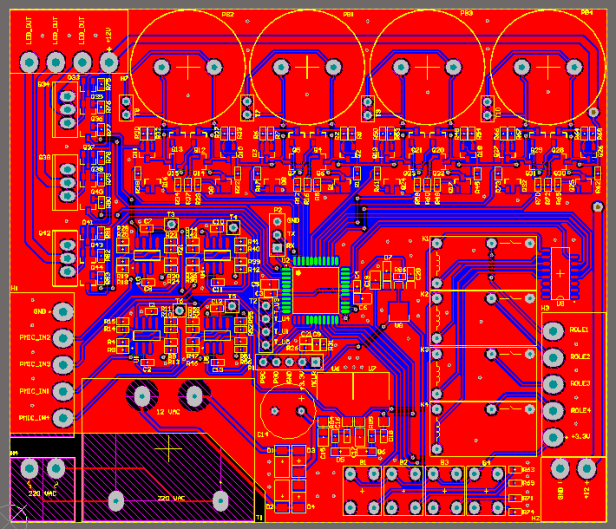
Bottom copper:
PCB with parts explained: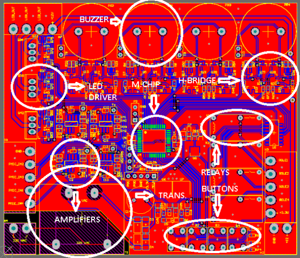
3D visualization of the finished project: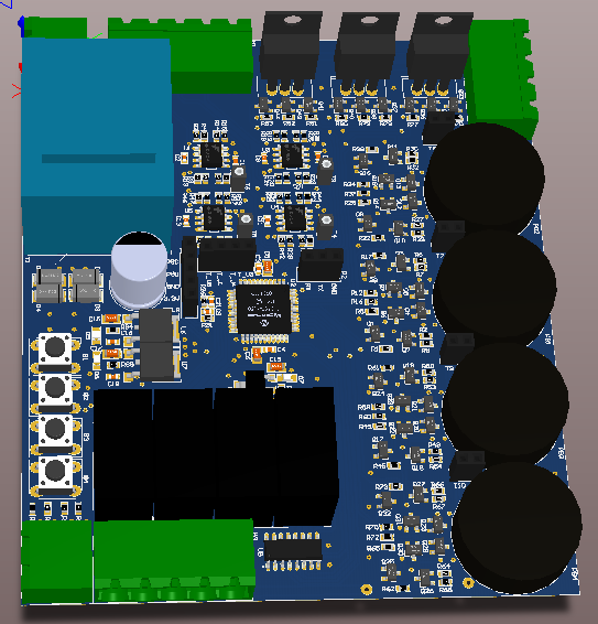

Bottom:

